Tuesday 21 August 2018

Making the ignition programmable


Fitting a programmable ignition to the TR6
One of the potential issues with fitting a supercharger to any car is the potential to trigger pre-ignition (sometimes known as Pinking or Pinging). Pre-ignition is an uncontrolled ignition of the air/fuel mixture in the cylinder (there is a good discription in Wikipedia.) In a normally running car the mixture is ignited by a spark at the spark plug at the correct time in the engine cycle to deliver power. The ignition is initiated at a single point (the spark) ensuring that the progress of the resulting fuel burn occurs in a direction in the cylinder that provides power and doesn’t damage components in the engine. In the case of pre-ignition the fuel is not ignited by the spark but instead ignition occurs as a result of heat within the combustion chamber. This can happen due to increased compression ratio, something that occurs when a supercharger is used to increase the pressure in the cylinder. It can also be induced by the increased charge temperature that occurs when air is compressed by the supercharger. This uncontrolled ignition does not provide a smooth burn of fuel instead the detonation is chaotic leading to uncontrolled pressure waves that can damage pistons.

So how to prevent pre-ignition?
There are a number of methods to prevent pre-ignition. For example one can reduce the compression ratio or cool the charge by using an intercooler or by injecting water or methanol into the charge. This latter method reduces the charge through evaporation of the water/methanol. However there is a much simpler method that involves retarding the ignition at boost. However to achieve this one has to have a system that is able to sense the manifold pressure and alter the timing accordingly. Unfortunately the old Lucas mechanical ignition system is not able to do this. One option would be to completely replace the ignition (including the distributor) with a fully electronic version (e.g. Mega Jolt or similar) but these systems require a method to sense what part of the 4 stroke cycle each cylinder is at. This normally takes the form of a crank trigger that uses a slotted crank pulley and a sensor to determine the position of the crank. Although I have used such a system on a Lotus Twin Cam I felt something simpler would be better.

The Aldon Amethyst System.
Looking around the market I discovered that Aldon (just up the road from me) had developed a programmable ignition system that uses the existing distributor to provide information on the position of the crank.  Really helpfully they also make a version of the system that senses manifold pressure. The system itself just takes the form of an ubiquitous black box (about the size of a large matchbox) with some wires coming out of it and a port for a tube from the manifold. Wiring it up was relatively simple.  +12v and ground wires which I connected to the fuel pump feed and chassis using the wiper motor mounting.

Plus 2 wires, green and yellow that connect to the black lead from the distributor and negative terminal of the coil respectively.


There is a final wire that can be used to swap between two maps or to activate an immobiliser.

Once hooked up you have to alter the timing of the distributor such that an LED on the black box lights when the crank is at the required static timing.
To achieve this I rotated the crank to 11 degrees BTDC with both valves on cylinder 1 closed (e.g. The compression stroke). Once set I turned over the car and she fired up nicely.

Now to program the ignition.
The black box also has a MiniB USB port  to allow communication with a laptop. I connected the port to my laptop using an appropriate wire, then fired up the laptop upon which I had downloaded the Amethyst software. A quick note about the software, it comes as a JavaScript and didn’t start on my laptop until I had installed a new version of Java. Once started the user interface is pretty clear.

As you can see in the figure, you have to set the number of cylinders (6 in this case of course). Then you have settings for timing advance at 500 rpm intervals up to 7000 rpm. You can also set advance or retard for different manifold pressures. Usefully this also includes pressures less than atmospheric allowing you to advance the timing at cruise helping with economy. There is also a rev limiter. The program works real time showing the rpm and timing and all settings can be saved onto 8 spaces on the black box or onto the laptop as named files. Now the problem with all these parameters is where to start.

Mistake one: I thought it would be nice to have the ignition settings on the software match the real advance at the crank. To achieve this I set the distributor with 0 degrees static and instead added the static onto the settings on the program. What I hadn’t realised is that as the program does not have a setting for 0 RPM during starting (where the RPM provided by the starter motor is < that 500 rpm) the system doesn’t supply enough advance. Result, coughing and backfiring from the engine. I quickly added back the static advance (11 degrees BTDC).

I then used the curve provided in the TR6 workshop manual to provide initial settings. The car ran OK with no pinking. To see what would happen I added some advance by increasing the offset setting. This shifts the entire ignition curve (like turning the distributor). As I advanced it I began to get some pinking under load so I retarded back to a safe level. I also added 4 degrees of advance at manifold pressures < atmospheric. At this point I spent some time playing with the advance curve itself. All looked very good.

Mistake two: I am lucky to have a Shell petrol station near by and always use Shell Optimax in the car. This has a higher RON number (roughly equivalent to the Octane level) than normal fuel. Increased RON reduces the likelihood of pre-ignition which is clearly a good thing. However on a recent holiday to Cornwall I was forced to fill up on petrol with a lower RON. Result, pinking under load. Oh well back to the drawing board. Reconnecting the laptop (yes I took it on holiday) I readjusted the centrifugal advance curve to reduce advance below 2500 rpm and pinking disappeared. Result! The final figures being those shown in the figure of the Aldon software above.

 Overall impressions. The Aldon Amethyst system is easy to use and works well. The ability to tweak the ignition curve is a two edged sword. On the one hand it allows you to get the curve you need. However on a number of occasions the shear number of parameters that you can change has led to me “over adjusting” loosing the sweet spot that I had previously attained. However the ability to return to a previous setting by loading in a previously saved map solves this issue. However it is important that you save makes regularly. Ironically the boost retard feature has been least use as the modest boost I am running (4psi) is not high enough to cause issues. Particularly given the low CR head I install later in the blog.

Tuesday 2 January 2018

Adventures with a Holley pt II

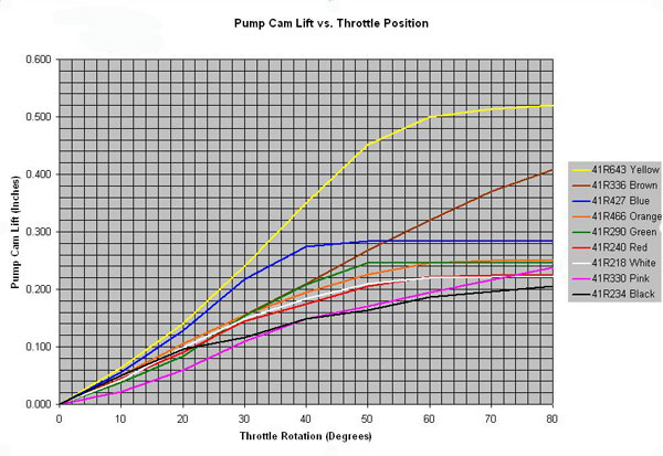
Now as I said there are only a relatively few cams available from Holley. They are all identified by colour and to me at least follow no specific trend. Is suspect they are the result of tuners playing around to find things that work. In actual fact the cams should be relatively easy to classify (and in fact there are a load of graphs online that show cam deflection as a function of throttle shaft rotation (see below).

Image result for holley accelerator cam graph

As you can see some cams will clearly deliver less fuel than others while some deliver more fuel at small shaft rotations and others provide a more even delivery until the throttle is fully open. However, a note of caution in analysing these curves. The cams can be mounted using 1, 2, or even 3 different holes meaning that the start point will be different for different mountings. None of the graphs take this into account. This is probably because it is also possible to bend the arm that runs on the cam transferring the cam shape into fuel delivery. The cam fitted to the Moss setup was the black one which gives a pretty large total delivery. 

The data from the AFR showed that the engine was particularly weak at throttle opening from low speed (meaning that he throttle was being opened from almost closed). Immediate thought was that I needed more deliver at low throttle spindle rotation. Looking at the cam curves there seemed to be nothing that gave this although both blue and red were a little better. However substituting these made only small improvements. Then one of the other supercharged TR6 guys (thanks John) suggested turning the black cam around.. this means using the part of the cam that is not intended to be for metering the fuel pulse. However a close look at this part of the cam showed that the shape actually meant a large slug of fuel at low throttle opening.. (see data below. NB with 0.044" acelerator jet fitted) the bogging was reduced and the backfiring almost disappeared..

But it was still not good enough... I added the 0.050" acellerator jet and things improved further.

Looking again at the cam choice I realised that increasing the pump capacity to the larger pump would be the next step.. so I bought a larger pump kit.. Went to fit it and found that the carb already had it fitted... damn... money wasted! 

This was also interesting because this pump is not designed for use with the black cam, instead it has its own cams, brown and yellow... So I substituted the brown cam for the black one and things got even better.. Now only small hesitation when provoked (e.g. Punching the throttle from <1500 revs in 4th gear) and backfiring only occurred when warming up from REALLY cold weather.. job done I thought..

Tuning the supercharger (adventures wth a holley carb).

As you'll have seen from my previous posts I fitted an Eaton Supercharger to my TR6.
Ok so Moss sell (or used to) the supercharger kit as presetup to run with the TR engine. Of course this is only ever an approximate thing as every engine set up is different.. In particular the engines from the US have a lower compression ratio than those in the UK. There are also differences in camshaft, cam timing, exhaust manifold and ignition timing.. The list goes on...

So any preset system WILL be approximate and  WILL need fettling..

This was (is) certainly true for my setup..
Remember the engine block is a UK CP block with a triumph 2500 saloon camshaft (less overlap for the supercharger) and stock exhaust system with a US narrow inlet head so I wasn't surprised when the car ran pretty badly..
First thing that was clear was that it didn't like being cold.. pulling away with part throttle led to backfireing through the inlet.. luckily there is a pop-off valve.. but the bang is loud enough to startly rather unwary (ask my rally co-driver!). There was also significant bogging when the throttle was snapped open.. Sounds like it is running lean.. best to check so out with the AFR meter..


Most classic car people seem to trust plug reading, feel and reading tea leaves as a way to tune engines. I like something more analytical (I am a scientist after all) so I have an AFR meter. This allows you to monitor what is coming out of the tail pipe in real time alongside RPM and potentially manifold vacuum. These data together let you know what is going on inside the engine under different driving conditions.. I used this system very successfully to get the PI working so I thought.. lets try with the supercharger..

Well the first run confirmed my fears. Opening the throttle led to a transient period when the mixture when super lean (>20:1 air:fuel where the optimum should be 12:1-14:1 approx). (See graph below). This super lean mixture only occured when pulling away from standstill. You can even see at about 18 seconds where I feathered the throttle to preven the car bogging completely (with the mixture becoming slightly less lean. The rest of the trace where I pull through 2nd, and 3rd gears isn't bad, infact it looks like it is running too rich. You can however still see slight lean spikes as I change gears but they are within the working window (e.g. AFR <14:1). Happily, even with this bog in first gear the time taken to get from 1000 to 4000 rpm in first is pretty much on a par with the best I got from the PI system.


TR6 supercharger mixture
There were some other issues in other areas, but without sorting this pedestrians were going to have heart attacks from the backfires whenever I passed them and opened the throttle.. The carburettor on the supercharger is a Holley, a venerable peice of US engineering built to feed those big loping V8s found across the pond.. The carb itself is a fixed jet carb like a webber but unlike the UK SU. This means that there are multiple circuits (and jets) to handle different driving states.

See Video on tuning Holley Carbs

For the problem I had the accelerator pump circuit was the place to start. Now a bit of science... fuel delivery in carbs in general is governed by the vacuum in the Venturi of the carb throat. More air flow more fuel.. less air flow less fuel.. all works well at steady speeds, but most cars don't sit at stready speeds. Instead we accelerate and decelerate dependent upon road conditions. This makes the life of a carb challenging... particularly during acceleration when we really demand performance. When you snap open the throttle their is a sudden drop in air velocity before the engine picks up. This means that the fuel delivery from the carb no longer matches need and the engine goes lean and bogs. To address this in fixed jet carbs an accelerator pump is employed. Think big water pistol full of petrol pointing down the carb throat.

 See video explaining Holley accelerator pump

When you stamp on the throttle the accelerator pump delivers a preset slug of fuel covering the transient weak mixture.. In my setup it wasn't doing this. Or at least it wasn't giving a big or long enough slug.

On the Holley the accelerator pump is governed by 3 elements, a plastic cam that acts like your finger on a water pistol translating the movement of the throttle spindle into a squeeze of the accelerator pump "trigger". The accelerator pump which is a rubber bellows which can be two sizes each giving a different size slug and the accelerator jets through which the fuel is delivered. This later component influences the length of the pulse. A large jet delivers a short but large slot and small jet delivers a longer shot with less fuel per unit time althought the total amount delivered but the two jets will be the same for the same setup.

So lots of things to play with, there are 2 pump sizes, 12 jets and 8 cams making 128 possible combinations!


If it takes 10 minutes to make it change and 20 mins to  do a run in the car to test the setup then it is going to take more than 60 hours or  2 1//2 daysfull time to test all possible combinations.

I may be committed but NOT that committed so I decide to optimise one thing at a time.

First the jets. My kit was fitted with an 0.044" jet. I decided to increase its size to 0.050" see if this improved things at all.. As you can see there was a improvement, AFR when pulling away is now 16:1. So I figured that perhaps there wasn't enough squirt.

To Be Continued

Saturday 9 December 2017

Car now pretty much back together..

Been 6 months or so since my last blog post.. Been doing odds and ends on the car sorting various hitches. Have fitted a tan interior which looks rather nice.
Still some more triming to do.. for example not sure whether to use the original moulded dor caps.. at the moment I have stuck some closed cell foam on with a view to covering it with vinyl which matches the trim. Also aiming to have the MX5 seaths retrimed to match.
Outside of the car looks reasonable.
just needs rear decals adding..
The refurbed grill looks good and tidies the front end..
As does the back. the paint shop didn't paint the black on the boot lid sill.. have sorted that now.. also need to add the rear badge.. want to changed the "injection" badge for "supercharged" somehow
Dash has come up nicely..

and finally the supercharger is looking at home..
have added a spectre inlet manifold which means cool air from the front and it looks more like it is meant.. I'll do another blog on the fun I have had tuning it!

Saturday 6 May 2017

The big reassembly

Now the car was back in the garage it was time to start the reassembly process. Pretty much everythink went back on reasonbly easily (helped by labelling of all the bags that had the parts in them). I fitted the aluminium firewall to the rear of the cockpit and sealed the edges with polyurethane sealant
Should provide some protection should the tank rupture in an accident.
Also fabricated a propshaft tunnel cover out of aluminium to replace the ropey cardboard original
You can also see the new plastic gearbox tunnel which fitted well after a little fettling. I also managed to replace my lucas wiper switch with a proper "clear hooters" switch. The switch was actually a fan switch from a GT6 but I rubbed off the fan emblem with wet and dry paper. Then printed the correct emblems onto some transfer paper and slipped them onto the switches.. not perfect, but not too bad.
Also fitted a light tan interior (decided against black as I'd like the lighten the interior a bit.
Also fitted Mazda MX5 seats. They are currently in black velour, but if they suit me I have some tan vinyl and will get them recovered to match. My only impression at the moment is that there is a little less leg room as the headrest interferes with the rear roll over bar. I also fitted the injection system to the engine, but again it seemed not to idle well and the injectors needed a fair bit of bleeding. bit depressing so left it for a while and concentrated on the interior...... AND THEN

A Moss supercharger kit became available!

If you read the earlier posts you'll know that that aim had been to fit a Moss supercharger kit. I had fitted a camshaft to suit the supercharger and had reconditioned a low compression cylinder head to allow big boost. And then Moss discontinued the kit due to a lack of carburetors. Anyhow early February and a second-hand kit appeared on Ebay. I thought long and hard about it and then bought it! They are never going to make these again and so chances are I would not see one for sale again.
this one came from a re-imported US car and was hardly used. Even better it came with a head (the kit was for the narrow inlet head only used on early cars). So removed the PI, removed the old head.
Fitted the supercharger
Added the drive belt system (including new crank pulley, waterpump and alternator in addition to two idler pulleys.
 And added the fuel pump, replacing the Bosch PI system and PRV. I used the original PI supply pipe from the boot to the engine bay. I used the PI filter and also fitted a filter just before the carburetor


Then after some playing around with the timing and idle fired it up.

 
Unfortunately it didn't idle to well (sticking at 1500 rpm) de ja vue from working with the PI system. This was probably due to a vacuum leak from the manifold. So a bit of checking a solved by sealing the manifold to cylinder head gasket with some silicon sealant and replacing the servo which was leaking (perhaps this was why the PI failed to idle properly!)

Interestingly I also ran it with the rocker over off and you can clearly see some of the pushrods rotating as they run.


So all pretty good. The car seemed to idle well but when I finally got to drive it it "bogged" really badly when snapping... Damn....

Saturday 24 December 2016

Back from Respray

Apart from cleaning and servicing the various components that came of the car during the strip down it has been a rather quite 6 months while the TR has been in for respray.
You may say 6 months is a long time, but I knew the summer was going to be busy at home so I said that the guys at Cartech in Kenilworth could take their time!

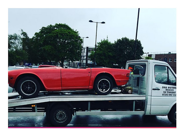
I have always thought that choosing to respray a car, although a great thing to do, always opens a hole load of cans of worms. For example, do you strip the car back to bare metal or do you leave the old paint be? The former means that you truly know what is underneath and the lines seem sharper, the latter is easier and cheaper. In the past I have always done bare metal resprays, but this time I decided not to as I didn't have the time to strip off all the paint. You also have to choose the colour of the car and what paint, solid or something with a clear coat on top. For a while I fancied a change to something like gunmetal grey, but eventually I decided to go with the original pimento, solid with no clear coat. The reasoning being that I liked the idea of keeping it factory and clear coated cars seemed too glossy. Anyhow off the car went on the back of a low loader.


Around November the spray guys started the work. They seemed to be much more sensitive to panel shape and found a whole load of minor dents that I couldn't even see. First to be sorted were the outer panels.
Which were then put into primer.

The rear wings where then mounted on the body and aligned. The chaps were a little concerned about how to get the alignment right and ended up talking to people in the states with expertise in rebuilding TRs. In the end to my untrained eye they got a pretty good result.
Then the body was primered and flatted back


And finally the topcoat was applied (now the car was looking great!)


The body shop then suggested that they deliver the car back to me to allow me to assemble it. From experience they new that often the bodywork gets the odd chip during reassembly. They then want the car back to sort any chips, paint the rear panel black and give the paint its final polish.
So the car duly returned on another low loader.


Now my job begins.. putting everything back on the car!

Sunday 12 June 2016

A fight with a TR6 heater

So, as the car is being pretty much totally disassembled for the respray I thought it would be a good time to rebuild the heater. After all it is pretty much "buried" deep behind the dash and my heater motor had been droning for a while. So job one... remove the heater. this entails.
1)  removing a load of stuff that is under the dash
2)  disconnect the cable from the heater control on the dash
3)  disconnect the heater pipes (air and water). Beware of flooding the footwell with water!
4) unbolt the 4 bolts that attach the heater to the firewall..

Simple! or perhaps not.. all went well until stage 4 and then 2 of the bolts (that point upwards and attach to captived nuts "inside" the upper part of the fire wall sheared. Bu^&er! Deep breaths!! will sort that later.

withdrew the heater from under the dash and had a look at it.
As you can see it is not really what's called high tech. It is essentially a biscuit tine with pipes coming out of it. Two small ones for water and 4 large ones for air (you can only see 2 in this picture). The lower one is cold air (it is before the heater matrix) and the upper one on the right is hot air (after the heater matrix). There is also a motor (hidden under the dome on the left) and a flap on the right which (in theory controls where the air goes). I continued to take it apart (fairly easy if the self tapping screws that hold it all together are not rusted up!)
And heres's the motor (two speed) and fan. Now I knew the motor was a bit iffy and there was certainly some play in the bearings. So I looked at the price of a new one and had  to sit down "how much!!".. to calm down I did a bit of trawling of the internet and found some inventive people across the pond had found a cheaper equivalent motor. Where did they find it? from a school bus of course!
Link to alternative TR6 heater motor. It has the same shaft diameter as the Lucas one in the TR. is two speed but without the external resister found on the TR version.. and best of all it was less that £20. Only issue would have been shipping, but I was working in the US in the next few weeks. So here it is in comparison to the Lucas item.
You'll see the size is about right. Note there is no shaft on the lucas one (left) as I had to cut it off to get the fan off. The only thing that is missing is the mounting flange. However I managed to rig one up using in jubilee clip (that was large enough to go around the complete motor body) and then a set of small "L" shaped brackets. Works great.

then connect to a battery for a test and wow.. what a difference.. the motor is smooth and silent and the power... amazing!

Next I stripped all the old paint and rust from the "biscuit tin" and then reassembled including new bits of foam around the heater to ensure that the maximum amount of hot air goes through and not around the matrix. (I use closed cell foam which comes on a roll for going under laminate floors, its cheap and self adhesive).

The final piece in the heater jigsaw is the heater flap. In theory I think the idea is that in one position the flap (and its foam backing) shut off air going through the heater forcing all the air (cold) out of the dash vents. In a second position the flap uncovers the pipes on the hot air side allowing air to flow to the demist and under dash vents. I think there is a third position (or at least there was in mine) with the flap fully down and poking out of the "biscuit tin". In this position the hot air was directed out of the bottom of the heater to the feet. All great in theory but position one didn't work because the foam had disintergrated (so new foam) and position 2 wasn't great as their were large gaps around the edge of the flap. This meant that the demist (perhaps the most important function was awful!).

So what to do... With a bit of lateral thinking I came up with a solution... draft excluders.. cheap (99p) and a MUCH better seal. I just cut them to size and riveted them in place.
Now all I have to do is refit.... But hang on... not so fast.. remember I had sheared two of the bolts that hold the heater in. you can see one of the offending studs pretty much below (the rusty patch on the front edge of the circular hole.

This is not going to be easy to drill out... So how about an easier strategy... weld in some replacement studs

Will need to tidy the welds.. but problem solved.